Francis turbine
Kaplan turbine
water turbine
Hydro Turbine
World Famous Hydropower
Hydrotu Hydropower
Sunday, December 29, 2019
Thursday, July 14, 2016
Monday, July 11, 2016
the progress block diagram of hydro turbine generator installation
the progress block diagram of hydro turbine generator installation
Thursday, June 9, 2016
Development of hydropower issues
Development of hydropower issues
a. Economics
The major advantage of hydropower is elimination of the fuel cost, immune to fossil fuels, such as oil, natural gas and coal with low construction and operating labor cost . The dam serves as multiple purposes.
b. Greenhouse gas emissions
Hydropower station does not burn fossil fuels, they do not directly produce carbon dioxide (a greenhouse gas). While some carbon dioxide is produced during manufacture and construction of the project, this is a tiny fraction of the operating emissions of equivalent fossil-fuel electricity generation.
c. Related activities
Reservoirs often provide facilities for water spots, and become tourist scenery.. In some countries, using dam for irrigation can support the fish farm and water supply. Large hydropower station can control floods, and be used for transportation.
2- Disadvantage
a. Damage to the environment
 |
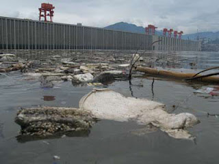
| pollutants at upstream of Three Gorges Dam |
Hydropower projects can damage surrounding or downstream ecosystems of the plants. In some cases, dams have been demolished due to the impact on fish. It can lead to scouring of river beds and loss of riverbanks. In addition, it also has impact on birds. Since building dam for agricultural and energy use, many native and migratory birds have become increasingly endangered.
b. Population relocation
Hydropower station has the need to relocate the native people, whose history and culture sites may be flooded and lost. Such problems have arisen in the Three Gorges project.
3-Comparison with other methods of power generation
Compared to nuclear power, hydropower generates no nuclear waste and leaks. Unlike uranium, hydropower is a renewable energy resource. Compared to wind power, hydropower plants are predictable, which can be easily regulated in power demand. Compared to fossil-fueled power plants, hydropower stations take a long time to build. Unlike combustion turbines for fossil-fueled, which can be economically developed, hydropower production is limited; due to climate change Long-term energy production may be affected. Hydropower may incur additional cost to ensure availability of sufficient power in years lacking of water.
Sunday, May 15, 2016
Bieudron power station
Bieudron power station-The world's highest water head hydroelectric Plant
today, let me introduce the world's highest water head hydropower station to every one. it's name is "Bieudron power station".


The Bieudron Hydroelectric Power Station is a hydroelectric power plant located in the Swiss Alps in the Canton of Valais in Switzerland. The power plant is fed with water from the Grande Dixence Dam's reservoir, Lac des Dix and is part of the Cleuson-Dixence Complex. The 1269 MW power plant is operated by Grande Dixence SA.
Bieudron hydropower station unit parameter
| ||
item
|
unit
|
value
|
Max. Water head
|
m
|
1883
|
Each capacity
|
MW
|
420
|
Water turbine type
|
Pelton
| |
speed
|
r/min
|
428.6
|
Rated flow
|
m3/s
|
75
|
Turbine runner diameter
|
m
|
4.65
|
Turbine weight
|
t
|
120
|
nozzles exit flow velocity
|
km/h
|
690
|
generator rated capacity
|
MVA
|
465
|
Rated voltage
|
kV
|
21(±10%)
|
Rated frequency
|
Hz
|
50
|
Generator stator weight
|
t
|
281
|
Generator rotor weight
|
t
|
454
|
Installation capacity of power plant
|
3×420MW
| |
total investment
|
billion dollar
|
0.8
|
《ABB Review》1994,No.10。
| ||
This facility houses three Pelton turbines, with each turbine rated at 423 MW (~567,000 HP); note that the turbine acceptance testing process reported a maximum turbine output power of 449 MW each (~602,000 HP) due to better than expected efficiency and ideal test conditions.[1]
 At the rated power of 423 MW each turbine operates at a head of ~1869 meters (6130 feet) and a flow rate of 25 cubic meters per second, with an efficiency in excess of 92% (~92.37%). The turbine assembly is a five-jet configuration; the stream of each jet is 193 mm (7.6 inches) in diameter with an exit velocity of 192 meters/second (630 ft/s). The kinetic energy of each of the 5 streams (i.e. 1 from each jet) is approximately 92.16 MW (Q = 5 cubic meters per second, v = 192 m/s, H = 1869 m). The assembly rated pressure is 203.2 bars (2944 psi).
The combined flow rate for the three turbines is 75 cubic meters per second. The facility peak power production is ~1269 MW. The turbines and associated valves were designed and developed by VA Tech of Switzerland.
On December 12, 2000, at approximately 20:10, the Cleuson-Dixence penstock, feeding the Pelton turbines at Bieudron, ruptured at ~1234 meters AMSL (under more than 1000 meters of head). The failure appears to have been due to several factors including the poor strength of rock surrounding the penstock at the rupture location. The rupture was approximately 9 m long by 60 cm wide. The flow rate through the rupture was likely well in excess of 150 m3/s (5,300 cu ft/s). The ensuing rapid release of a very large quantity of high pressure water destroyed approximately 100 hectares (1 km²) of pastures, orchards, forest, as well as washing away several chalets and barns around Nendaz and Fey. Three people were killed.[2]
The Bieudron facility was inoperative after the accident; however, it became partially operational in December 2009, and fully operational in January 2010. Much investigation went into the accident resulting in the almost complete redesign of the penstock. Legal action is still in process and the root cause of the rupture is unknown.
However details regarding the redesign are available. The redesign calls for improvements in the pipe's lining as well as the addition of grouting around the penstock to reduce water flow between the penstock and the surrounding rock due to dynamic variation of the pipe diameter during operation (it expands due to water loading during operation then contracts when the load is removed, leaving a gap). The damaged section of the penstock was rerouted around the previous location to where new (undamaged) more stable rock is available. Construction on the redesigned penstock was completed in 2009. Redesign considerations include operational control of maximum agreed design limits under all conditions of assembly, design and service conditions (including water hammer pressure spikes).
https://en.wikipedia.org/wiki/Bieudron_Hydroelectric_Power_Station
Sunday, April 24, 2016
Turgo turbine
Impulse Type Turbine Turgo Hydro Turbine
The turgo turbine is a kind of impulse turbine and suited for heads from 50m-250m, between Francis turbine and Pelton Turbine.The feature is an angle of 22.5° is formed between the center line of the nozzle jet and the rotational plane of the runner. The water from the penstock is transformed into a high speed jet through the nozzle. The water is directed obliquely to one side of the runner and discharges at the other. The dynamic force of water flow makes the runner rotate rapidly.
It consists main turbine runner, nozzle assembly, conduit part, deflector control and hydraulic etc.
Turbine runner is the principle part of the turbine. runner made of casting stainless steel. It has influence over the characteristic of the turbine. The runner consists of vanes, the hub and the outer ring of runner. The shape of vane is three dimension camber. The outer ring applies to strengthen the runner and to reduce the loss of wind.
The plane key set up between the runner and the main shaft in order to transfer running torque. The elastic coupling is fitted on the end of main shaft. The end of main shaft and the hole of coupling are fitting and transfered the running torque by plane key.
Hydroelectric Generator
Hydroelectric synchronous generator for Hydro Turbine
The generator is of synchronous in horizontal or Vertical arrangement. Main parts of the
generator consist of stator, rotor, bed-plate and so on. The generator unit shall be
supported by one radial bearing and one thrust bearing, mounted on a bed-plate.
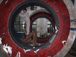
The stator frame consists of welded steel plate construction. The stator core is stacked with high-grade, non-aging, low-loss, thin laminated silicon sheet steel. The laminations shall be coated on both sides with a superior quality insulating varnish to minimize eddy current losses.
The core laminations are firmly and uniformly clamped together by means of clamping ring, tooth supports and bolts passing the stator frame to prevent loosening in service or causing undue noise or vibration due to magnetic force.
 The stator winding adopt double-layer mode and Y-type connected with the main leads and neutral end leads. Each strand is thin square copper wire insulated with spun glass. The coil shall be insulated between turns and to grand by power mica tape bonded with epoxy resin having excellent electrical properties. The outer layer of the coils shall be treated with semi-conducting compounds to prevent corona. Corona protection shall be also provided on a portion of the end-windings. The insulation is of class F.
In order to measure the temperature of stator winding, The resistance temperature detecting elements are embedded in the stator slots of the generator.
The generator rotor is of salient pole. The rotor yoke coupling is fixed on the main shaft through heated method.
The field coils are wound edgewise with copper strap. Superior quality insulated material is inserted for insulation between each turn. The completed coil is then placed in a fixture, heated up and pressed simultaneously until a solid and well bonded coil is reach. The insulation is of Class F.
The main shaft is made of high quality forged steel and has sufficient safety dimension so that it shall not cause harmful vibration and deformation at any speed including the maximum turbine runaway speed. The fan shall be mounted on both side of the rotor.
Subscribe to:
Posts
(
Atom
)


