TRENDING
Showing posts with label it. Show all posts

Sunday, April 24, 2016

Turgo turbine

Impulse Type Turbine Turgo Hydro Turbine  

The turgo turbine is a kind of impulse turbine and suited for heads from 50m-250m, between Francis turbine and Pelton Turbine.
The feature is an angle of 22.5° is formed between the center line of the nozzle jet and the rotational plane of the runner. The water from the penstock is transformed into a high speed jet through the nozzle. The water is directed obliquely to one side of the runner and discharges at the other. The dynamic force of water flow makes the runner rotate rapidly.
 

turgo hydro turbine
It consists main turbine runner, nozzle assembly, conduit part, deflector control and hydraulic etc.
Turbine runner is the principle part of the turbine. runner made of casting stainless steel. It has influence over the characteristic of the turbine. The runner consists of vanes, the hub and the outer ring of runner. The shape of vane is three dimension camber. The outer ring applies to strengthen the runner and to reduce the loss of wind.
The plane key set up between the runner and the main shaft in order to transfer running torque. The elastic coupling is fitted on the end of main shaft. The end of main shaft and the hole of coupling are fitting and transfered the running torque by plane key.

turgo turbine runner


turgo water turbine


Hydroelectric Generator

Hydroelectric synchronous generator for Hydro Turbine

hydropower generator

    The generator is of synchronous in horizontal or Vertical arrangement. Main parts of the
    generator consist of stator, rotor, bed-plate  and so on. The generator unit shall be
    supported by one radial bearing and one thrust bearing, mounted on a bed-plate.

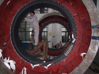
generator stator
The stator frame consists of welded steel plate construction. The stator core is stacked with high-grade, non-aging, low-loss, thin laminated silicon sheet steel. The laminations shall be coated on both sides with a superior quality insulating varnish to minimize eddy current losses.
The core laminations are firmly and uniformly clamped together by means of clamping ring, tooth supports and bolts passing the stator frame to prevent loosening in service or causing undue noise or vibration due to magnetic force.
generator windingThe stator winding adopt double-layer mode and Y-type connected with the main leads and neutral end leads. Each strand is thin square copper wire insulated with spun glass. The coil shall be insulated between turns and to grand by power mica tape bonded with epoxy resin having excellent electrical properties. The outer layer of the coils shall be treated with semi-conducting compounds to prevent corona. Corona protection shall be also provided on a portion of the end-windings. The insulation is of class F.
In order to measure the temperature of stator winding, The resistance temperature detecting elements are embedded in the stator slots of the generator.
The generator rotor is of salient pole. The rotor yoke coupling is fixed on the main shaft through heated method.
The field coils are wound edgewise with copper strap. Superior quality insulated material is inserted for insulation between each turn. The completed coil is then placed in a fixture, heated up and pressed simultaneously until a solid and well bonded coil is reach. The insulation is of Class F.
generator rotor

The main shaft is made of high quality forged steel and has sufficient safety dimension so that it shall not cause harmful vibration and deformation at any speed including the maximum turbine runaway speed. The fan shall be mounted on both side of the rotor.
small generator


S type Turbine

Hydro Turbine S Type Turbine for Hydropower Project

S type turbine is suitable for heads from 2m to 20m and large discharge hydropower station.
S-type tubular turbine is available in versions of Horizontal Kaplan, also called S-type horizontal Kaplan.
lts feature is that the water flow is axial throughout the passage from the inlet to the outlet, so that the passage is a straight conduit essentially.The turbine shaft passes out of the tube at the point where the tube changes direction, installation is ether with the transfer belt or directly connected to the generator. This modern turbine is characterized by high efficiency in a broad band of flow rates.
S-type turbine is also consist of fixed runner blades and movable runner blades.
Rotating part consists of runner, main shaft, short main shaft, and transition flange. The rotating part is the important part of turbine; the potential energy and kinetic energy of water flow is transformed into mechanical energy, and then it is transmitted to generator shaft by main shaft and finally is converted into electric energy. Therefore, rotating part play the role of energy conversion and transmission.


Runner is the heart of turbine, and the conversion of energy is completed by runner. Therefore, it should have high efficiency, and excellent performance of cavitations erosion resistance to ensure economic and steady operation of unit; the blade of runner material is
ZG0Cr13Ni4Mo, molded line, wave steepness and surface toughness have been controlled strictly to ensure turbine in high efficiency state.  runner hub material is casting ZG230-450.
Main shaft is made of 45# forged steel; Transition flange is installed between main shaft and thrust shaft; so that the runner and main shaft will be disassemble without removing thrust shaft.
Kaplan turbine with adjustable blades


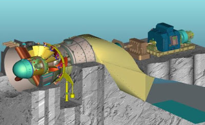
Layout drawing of S type water turbine


Pelton turbine

Pelton Hydro Turbine  for high water head Project

The Pelton turbine is widely used in hydropower station with the heads from 80-1000m.
Pelton turbine is consisted of runner, turbine case, nozzles assembly, inlet pipe, deflector etc. The runner is assembled in the shaft of the generator, torque transmission by ping.
lt utilizes the dynamic power of high pressure water flow to rotate the runner and force the rotor work, The centre line of the jet is in the same plane as the runner while rotating.
Pelton turbine has the advantages of compact construction, stable running and easy operation. Normally, Small pelton turbine always arranged with horizontal shaft and one or two nozzles,   Medium size and larger Pelton turbines are most often arranged with vertical shaft, and equip four or six nozzles to obtain more power.

1. Runner

The runner is the principle part of the turbine. It has influence over the characteristic of the turbine. The runner consists of vanes, the hub and the outer ring of runner. The shape of vane is three dimension cambers. The outer ring applies to strengthen the runner and to reduce the loss of wind.

The runner disc and buckets are CNC machined from and integrally forged 13%Cr 4% Ni steel, the faces of buckets which are in contact with water must be CNC machined and ground to a smooth surface with a maximum surface roughness of 0.8 Microns. The buckets  must be controlled by a coordinate measuring machine via a certified measuring company and must be submitted for approval. The center line allowance between the buckets is 0.57mm

Additional tests for material must be completed according to specification for Inspection of steel castings for hydraulic machines CCH 70.3. A detailed chemical analysis, Ultrasonic tests UT70.3, magnetic particle tests MT 70.3, and dye penetrant tests PT70.3 must be performed via a certified company and results should be submitted for approval.

Runner must be statically balanced according to ISO 1940/1 class G6.3 and G2.5.


2. The case and the cover of the case

The case used is a fine gradewelding steel with a minimum yield strength of 550 Mpa (St52 or equivalent), it has enough intensity and is convenient for maintenance. There is trachea on the case, which should be connected to the ventilating pipes from the tailrace channel and shall not use air from the power house. it is for complementing the air the jet takes, avoid vacuum in the house, keep the circulation, and there is a gate in the unit for overhauling, between up cover and down seat there is o-washer for overhauling.


3. Jet deflectors
Deflectors be manufactured from a monolithic stainless steel. Deflectors be
designed to withstand maximum discharge from the nozzle without vibration. The deflectors
be controlled by a double acting servomotor located outside the turbine casing.

4. Nozzle

The nozzle is components of the distributor of the pelton turbine.The intake pipe conduits pressure water flow to the nozzle via the guide support which is used to support the needle stem to provide against a vortex. In practice the nozzle is just a needle valve; however the valve plays a role of shut off and of transform energy in impulse turbine. The pressure water flow enters the nozzle body. Then the velocity of water flow shall be increased rapidly at the nozzle tip and the water flow is formed a jet to inject to the vanes of runner.
 So pressure energy of the flow changes to velocity energy and the runner does a work. The opening of nozzle shall be adjusted by nozzle control mechanism which is consisted distributing valve, the servomotor of needle and by combination mechanism. The operation oil pressure is 6.3Mpa, it used internal control structure, the opening of the needle is 75%~85% on the full-load. The server-motor piston and the piston rod is made of 35 steel welding.

Allowance of the position of the jet center line and the rotor pitch circle is ±1.2mm. Allowance of the position of the jet center line and the pelton watershed edge is ±1.2mm as per the IEC standards.

5. Needle control mechanism

The needle control mechanism includes a jet deflector; the jet deflector is also called deviator. It is used to deflect the jet on a sudden load rejection in order to avoid run away of the unit and pressure over rise for excessive water hammer in the penstock.


Kaplan turbine

Axial Flow Turbine Kaplan Hydro Turbine / Kaplan Water Turbine for Water Head 2m - 70m Hydropower Project

The Kaplan (axial-flow) turbine for low head from 2m to 70m. This type of turbine is mostly suitable for hydropower stations with low water head and big flow.
lts feature is that the water flow passes through the runner axially. The axial-flow turbine can be classified into two forms according to the runner construction: one is fixed blades (Propeller) for small variation of head and power, the other is movable blades (Kaplan) for large variation of head and power.
The kaplan turbine with vertical shaft arrangement , with three types as open flume, pressure flume, and seal off (concrete spiral case).
Generally, Kaplan turbine is composed of distributor, guide vane, runner, draft tube etc. 


Main Structure of Kaplan Water Turbine

This hydraulic turbine is axial flow turbine with a vertical shaft. And its spiral case is made of metal or concrete.
The water flows through the channeling pipe, and then into the spiral case, which ensure that the water enter the turbine circumferentially and symmetrically, forming certain circumfluence quantum.
The water flows through the stay ring into the distributor, whose guide vanes can regulate the turbine discharge and the flow direction and thus make the water flow into the runner circumferentially and symmetrically. Consequently, the runner revolves and converts hydraulic energy into mechanical energy and then drives the rotor of the generator revolve by the force of the main shaft of the hydraulic turbine, thus converting the mechanical energy into electrical energy. The water, which has gotten out of the runner, flows to the downstream of river through the draft tube.
Because of the restoration of the draft tube, the energy of the water flowing out of the outlet, is partly reused, thus loss is reduced and efficiency is improved.


Main structures of the hydraulic turbine are described in the following.

Draft tube assembly

It includes draft tube straight cone and metal bend tube. Because of the restoration of the draft tube, the energy of the water flowing out of the outlet is partly reused, thus loss is reduced and efficiency is improved.


Rotating parts assembly

Rotating department is mainly composed of a runner, main shaft, radial turbine bearing and seals of main shaft. Runner with the blades of stainless steel of 06Cr13Ni4Mo assembled and welded. After having been mould into shape, all the  blades must be processed to the required degree of roughness and precision.
To ensure the stable operation of runner, a test for still balance is performed in the manufactory. Shared by the hydraulic turbine and hydro generator, the vertical main shaft, connects the runner with pins. The main shaft seal is of the type with soft graphite packing
The radial turbine bearing is water-lubricating elastic metal-plastics bearing,clean water,0.15~0.2Mpa.
kaplan turbine runner

Distributor assembly

Distributor consists of head cover, bottom ring, guide vanes, the regulating ring, transmission departments and any other parts. They are divided into two parts. One part includes guide vanes and supporters of three parts of shaft sleeves, namely bottom ring and head cover. The other part includes guide vane arm, conjunction rod, regulating ring, and pull-push rod of transmission departments.
distributor

a. Guide vane and its supporting parts.

There are  guide vanes spreading in a circle equally.

Guide vane is standard blade-shaped with positive curvature This enables the guide vanes to have the virtues of little hydraulic loss and high degree of strength as guide vanes opening varies. The Guide vanes are made of 20SiMn.On the bottom of guide vane, shaft sleeves are fixed with the bottom ring and they are self-lubricating bearings of thin plates of Fluon. In the head cover, shaft sleeves are fixed with the bottom ring and they are self-lubricating bearings of thin plates of Fluon.
Guide vanes

b. Transmission department.

Control ring is welded with steel plates, supported by head cover. On the joint surface are anti-grinding plates of nylon, which are used for guide in direction. There is pressing plate so that control ring wont go up. On the top, control ring are connected with two connecting rods. Below, there are 24 holes to pins, spreading in a circle equally. Control ring is connected with guide vanes through pins, connecting plates and guide vane arms.

The shear pins between the guide vane arms and connecting plates are the weakest part in the transmission department of guide vane. If guide vanes close with great difficulty, the shear pins are immediately sheared to protect other parts. Consequently the signaling equipment is sheared, and signal is sent.


Francis Turbine

Horizontal Francis Hydro Turbine / Francis Water Turbine with Water Head From 20m to 300m

Francis turbines are most widely used among water head from 20m to 700mm. A Francis turbine has a runner with fixed blade, usually nine or more. Water is introduced just above the runner and all around it and then falls through, causing it to spin. Besides the runner, the other major components are the spiral case, wicket gates, and draft tube. Most small Francis turbine are horizontal shaft and metallic spiral case, it has two bearing assembled on the generator seat.

Water flows through penstock of the power station, Butterfly valve, expansion pipe, inlet tube, spiral case and wicket gates into the runner, and then it drives the runner to revolve and convert hydraulic energy into mechanical energy and drives the rotor of generator revolution by the force of the main shaft of turbine, thus converting the mechanical energy into electric energy.


Franics Turbine runner compose of the  blade, upper crown, bend and cone.
The whole rotating part is mainly composed of the runner, main shaft, flywheel and main sealing assembly etc. The main shaft is laid in horizontal or vertical  position. The runner cone is keyed on the end of the main shaft, and locked with bolt, The other  end of the main shaft is connected to the flywheel. The runner is the principal component of the turbine convert hydraulic energy into mechanical energy. The main sealing assembly adopts polyethylene packing structure to prevent water leaking out, and should be connected the clean and pressure water which pressure is 0.15~0.25MPa.


Spiral case

The spiral casing is the largest part of the hydraulic turbine and erecting bench- mark. It is made of steel-welding structure. Together with spiral casing and stay ring. Some stay vanes are equipped on the inner of stay ring. A pressure gauge is equipped to measure the pressure of the inlet water there. On the top of the spiral casing, it presents an air-discharge valve, which is used to expel out the residual air in the shell, when the shell is filled with water before starting up the turbine.


Distributor
The distributor consists of wicket gates, guide vane arms, shear pins, regulating ring, head cover, bottom ring etc.
 The wicket gates  function is to regulate the discharge of water flow. so as to suit the regulation on various loads.
 The opening of wicket gates can be regulated by the governor servomotor, to guarantee the revolving speed constant when the load changes. When the turbine is shut down all openings between the wicket from flowing into the runner. Each wicket gate swivels in bushing along, the axial line of its stem. The lower bushing seats in the head cover, the middle and upper bushing seat in the bottom ring. The connecting rod mechanism is equipped between the wicket gates and regulating ring in order to transfers their move and force.
Also the  shear pins are equipped on the distributor. When the turbine is shut down if the closing of the wicket gates exists obstacles, the shear pin related to the opening will be shorn so that the other pats of distributor many not be damaged. The regulating ring is connected with the servomotor by way of the connecting rod.


The draft tube  consists of draft tube, draft tube cone and draft tube bend etc. It’s function is to guide water current and receive some hydraulic energy.


Back To Top